Lewis Fromberg, PE
Mechanical Design Engineer - Powertrain Cooling
Kenworth Truck Co (2022-present)
About Me
Hello, I am a design engineer for Kenworth Truck Co. (PACCAR) in Seattle, WA. I work on powertrain cooling components with a focus on cooling performance, fan drives, cooling modules, and transmission coolers.
Skills
CAD
Creo Parametric (expert)
GD&T, assembly, analysis, clearance studies
Sheetmetal, castings, tubing, routings
FEA
SolidWorks: certified at level of associate (proficient)
GD&T, BOM, analysis
ANSYS (competent)
Static stress analysis, some CFD and heat transfer
AutoCAD
Programming
MATLAB (proficient)
Python (beginner)
Hard Skills
Soft Skills
GD&T
DFMA
Problem Solving
Team Leadership
Organization
Time Management
Thermal analysis/design
Large and small volume design
Goal Oriented
Communication of complex problems to strategic stakeholders
Self motivated
Projects
Thermal Analysis (Kenworth Truck Company)

As design lead on the new X15N engine program, I made the majority of new powertrain cooling parts and set up testing for thermal analysis to determine what ratings could be provided
When our engine supplier made late changes that cut coolant flow rate by 30%, I redesigned fan drives and recirculation shields to maximize available ratings, which were rechecked via CFD. All of this was done on an accelerated timeline, with only 6 months from when we learned about the low flow rate to SOP.


Installation Simplification (Kenworth Truck Company)
Problem: TX-18/XD transmission cooler, which were installed on the frame rail, required a lot of manual engineer input to determine a good location to place the cooler and appropriate line lengths. Additionally, this installation had to be installed in a busy area of the plant, after the engine was set in the frame rails. This would not be feasible in the future as annual usage was expected to increase exponentially.
Solution: Mount the transmission cooler to the transmission by piggybacking on the transmission support spring bracket. This design was $80,000 cheaper per year, could be installed in a much less busy area of the plant, and required no engineering input after implemented since all line lengths are consistent

Stationary Grille and Exaggerated Deformation Visual

Coolant Supply Manifold and Exaggerated Deformation Visual
FEA Projects (Kenworth Truck Company)
I have done multiple projects in which I have analyzed FEA results and/or done my own FEA analysis to determine first mode, stresses, and deformation of parts that I have designed
Projects include
Stationary grille FEA: a new stationary grille was needed rapidly after one of our cooling module suppliers informed us that they could no longer supply a cooling module that the previous design was mounted to. I designed and analyzed a new stationary grille that could mount to a new cooling module. This new design was honed through many iterations of analysis and redesign over the course of three weeks, leaving just enough time for manufacturing before being put on production trucks. It matched or exceeded the baseline of the old design in modal and stress.
Coolant supply manifold FEA: for a new engine program, a new supply manifold was made that attached to the back of the flywheel housing. The mounting of this supply manifold left the fittings in a cantilevered position, making the bracket a risk to break. I ran the FEA shown to the left and determined that the modal and bracket stress was adequate per our corporate standards

Hose Cutter Track Insert (Kenworth Truck Company)
Problem: Kenworth’s hose cutter had too many size 8 holes and not enough size 4 and 6 holes. This made it so the hoses had to be switched out of the 4 tracks for every truck.
Solution: I created UHMW track inserts so the extra size 8 tracks can be used to run size 4 hose. This design withstood all durability tests and was adaptable so it could be used for any size hose.
This design saved the plant $17,860 per year in the form of time saving

Full track insert CAD model
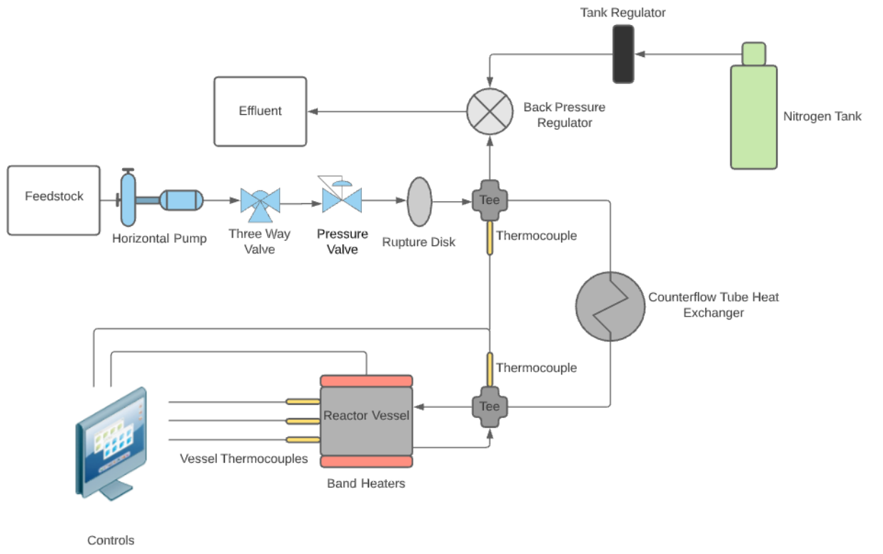
Research Reactor Vessel
-
The goal of this project was to create a reactor vessel that could destroy PFAS, a toxic “forever chemical”, in a simple and easily scalable design.
-
This reactor vessel made of inconel and is welded together to avoid PFAS’s corrosive effects on fittings. It pressurizes and heats the solution up to 350 degrees celsius and 3500 psi (just below supercritical conditions), which has been shown to destroy PFAS at a highly effective rate (up to 99.99% in an hour). I designed and manufactured the reactor body, chose heaters that could get up to temperature base on CFD models, and designed the connections between the heat exchanger and the reactor body so they could be easily and safely manufactured.
-
Currently, this reactor has been both pressure and temperature tested with water. It will be tested with PFAS in the coming months once the temperature control system has been calibrated.
-
This reactor provided a good base for temperature and pressure testing and can be used to calibrate PID systems as well as test how long welds in reactors like this can last. The next iteration that I am working on, which is currently in the design phase, will have electrodes to test how iron and electricity can affect PFAS destruction.
Education
University of Washington, Bachelor of Science in Mechanical Engineering (Graduated June 2021)
3.55 GPA, Dean’s List: 2017, 2018, 2019, 2020 (3x), 2021
Coursework in Mechanical Engineering Design, Manufacturing Processes, Machine Design Analysis, Advanced Energy Conversion, Material Science, Mechanics of Material, Heat Transfer, Thermodynamics, Fluid Mechanics, SolidWorks, Computer Aided Technology, MATLAB, Finite Element Analysis, Technical Communication, Renewable Energy
University of Washington, Masters of Science in Mechanical Engineering (Graduated Aug 2022)
3.66 GPA
Coursework in Continuum Mechanics, Engineering Analysis
Certificates
PE Mechanical: Thermal and Fluid Systems
SolidWorks: Certified Associate